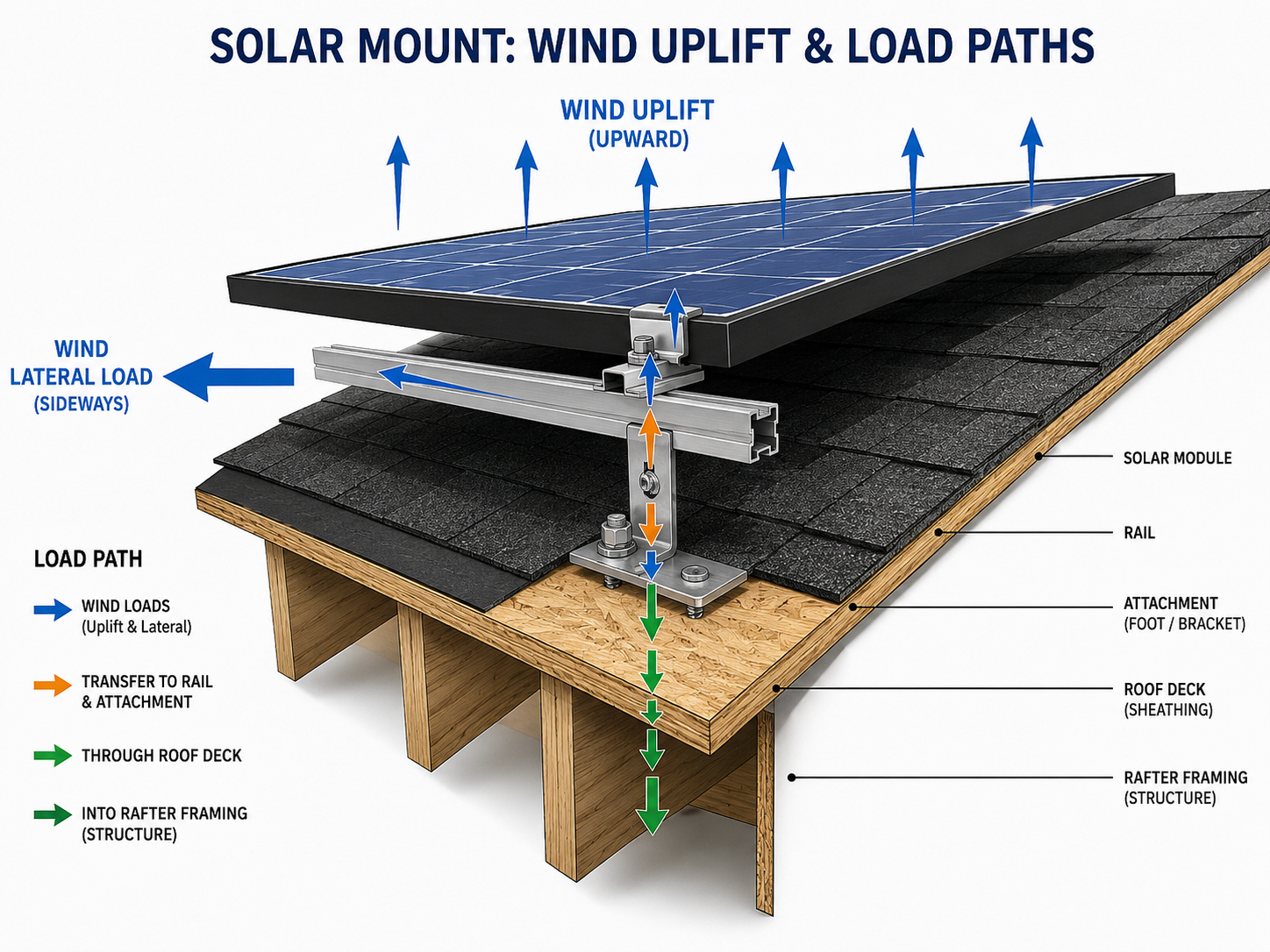
Forces through the system
Wind wants to lift the array. The load path must answer.
Solar mounting is not just about holding panels in place on a calm day. The system must transfer wind uplift, dead load, lateral forces, vibration, and service loads through an approved path into the roof, structure, ballast, posts, steel, or foundations.
Load path principle
The array is a chain of connections.
A solar mounting system is only as good as its weakest connection.
Wind and weight move through the system in stages: module to clamp, clamp to rail, rail to mounting foot or rack, mounting foot to rafter or structure, ballast to roof, post to ground, or steel frame to foundation. Each connection must match the approved plan, manufacturer instructions, engineering assumptions, and inspection requirements.
SolarMount.com rule: every solar array needs a credible load path. The finished system should make sense from module frame all the way down to the building or ground.

Force checklist
What forces does solar mounting need to resist?
Solar arrays face more than gravity. A real mounting review considers how the system behaves over time.
Dead load
Modules, rails, clamps, mounting feet, ballast, conduit, equipment, and service materials add weight to the roof or structure.
Wind uplift
Wind can pull upward on the array, especially near roof edges, corners, exposed fields, carports, and high-wind locations.
Lateral force
Wind can push sideways, creating sliding, racking, twisting, and vibration forces.
Thermal movement
Rails, modules, metal roofs, and structures expand and contract with temperature changes.
Service loads
Installation crews, inspectors, maintenance workers, and equipment handling can add temporary loads.
Long-term weathering
Vibration, corrosion, UV exposure, moisture, and repeated thermal cycles can test the mounting system over time.
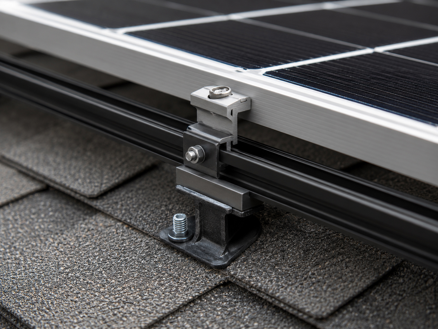
Module to rail
The load path starts at the panel frame.
Clamps and rails are not cosmetic hardware. They are structural links.
The module frame must be clamped where the module manufacturer allows. The clamps must connect correctly to the rails. The rails must span between supports according to the racking design. The array may look neat, but the important question is whether every force has a proper path into the support system.
Practical rule: do not judge a solar array only by straight rows. Ask whether the clamps, rails, spans, and support points match the approved design.
Common load paths
Different mounting methods transfer forces differently.
Roof-mounted, ballasted, standing seam, ground mount, and carport systems do not use the same structural path.
Sloped roof load path
- Module frame to clamps.
- Clamps to rails.
- Rails to mounting feet.
- Mounting feet to lag bolts or approved fasteners.
- Fasteners to rafters, trusses, or approved framing.
- Framing to the building structure.
Flat roof ballast load path
- Module frame to rack.
- Rack to ballast trays or supports.
- Ballast and rack to roof protection layer.
- Roof membrane to roof deck and structure.
- Building structure to columns and foundation.
- Wind resistance through ballast, friction, layout, and approved design.
Ground mount load path
- Module frame to rails.
- Rails to posts, pipe, or rack structure.
- Structure to driven steel, concrete piers, ballast, or foundations.
- Foundations to soil.
- Wind and dead loads resolved through engineered supports.
- Trenching and electrical pathways coordinated separately.
Solar carport load path
- Modules to racking and purlins.
- Purlins to beams.
- Beams to columns and bracing.
- Columns to footings and anchor bolts.
- Footings to soil.
- Wind, seismic, vehicle clearance, and drainage all reviewed together.
Important: this page is educational. Actual wind uplift, load path, ballast, racking, fastener, clamp, structural, foundation, and inspection requirements must follow the approved plan set, manufacturer instructions, engineering requirements, local code, fire code, and qualified professional judgment.
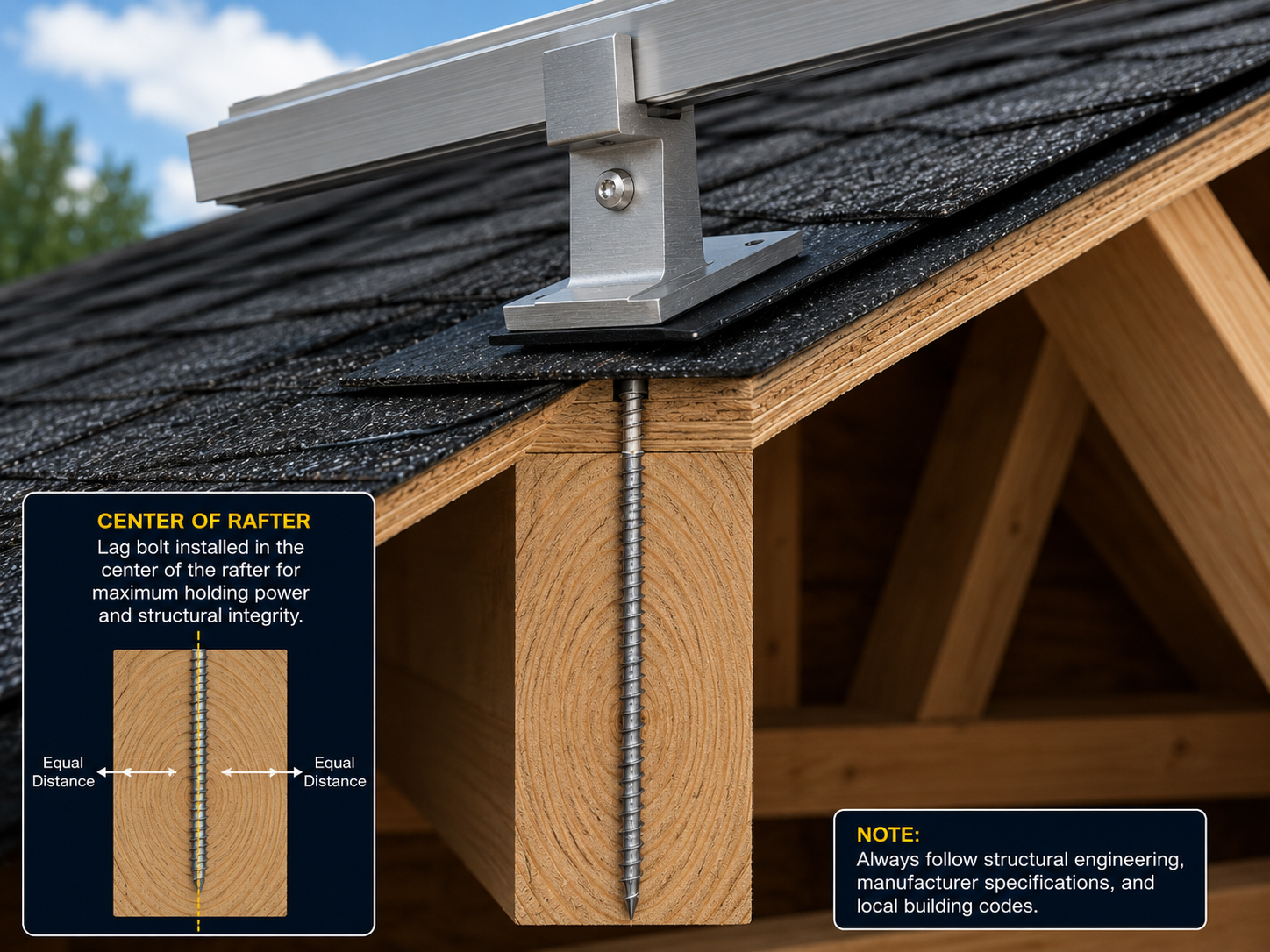
Rafters and attachments
On sloped roofs, the rafter often carries the story.
The roof covering sheds water. The structure below carries the load.
For many sloped-roof systems, forces move through mounting feet and fasteners into rafters or approved framing. That means rafter location, attachment spacing, fastener placement, flashing, and inspection timing all matter.
Confirm rafters or approved framing before drilling.
Fasteners and mounting feet must follow the approved plan and instructions.
Flashing and waterproofing must be verified before concealment.
Mounting types
Each mounting type has its own wind question.
The same wind can create different design problems depending on where and how the array is mounted.
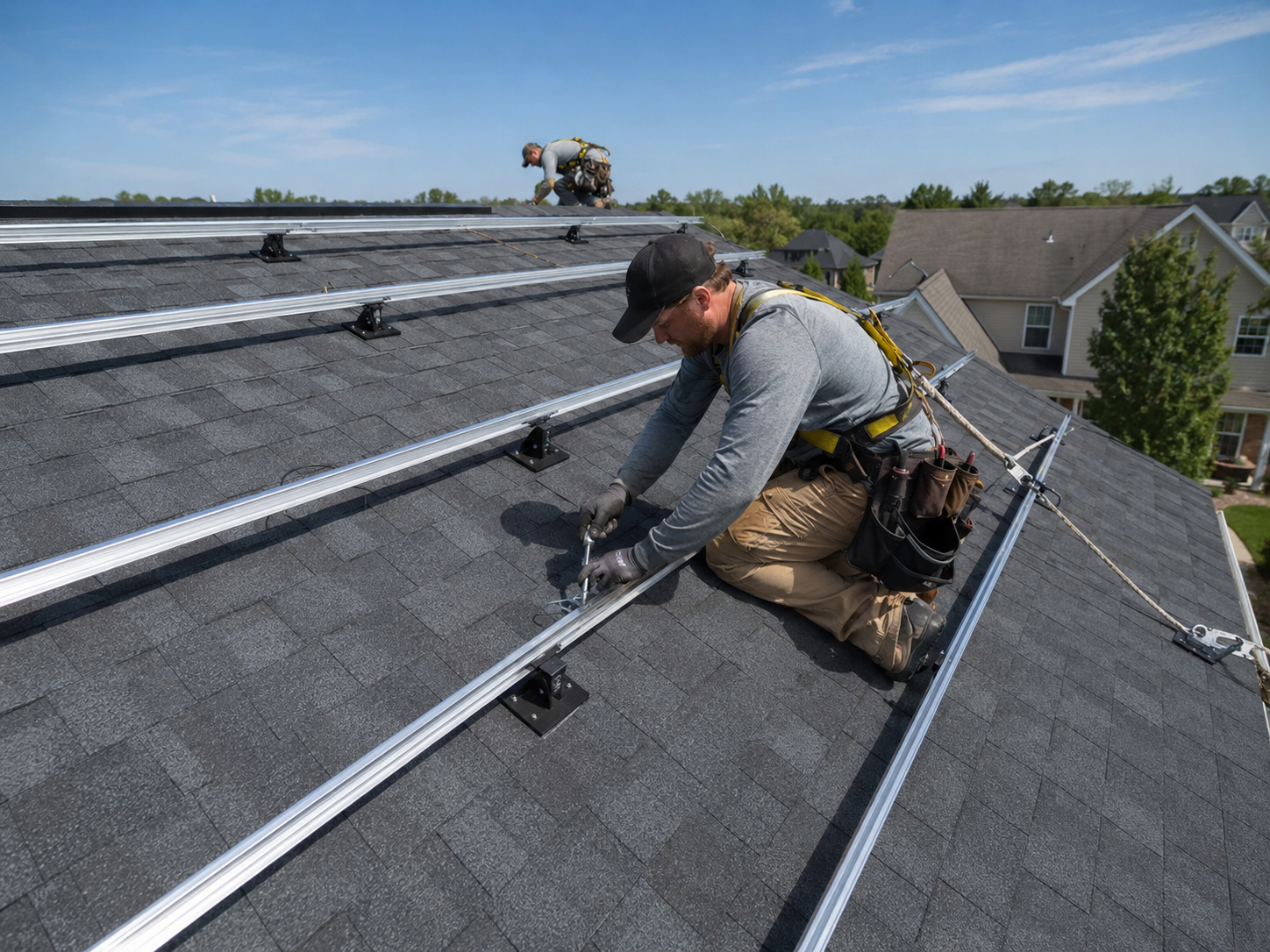
Composition Shingle
Wind loads transfer through rails, mounting feet, fasteners, and rafters.
Standing Seam
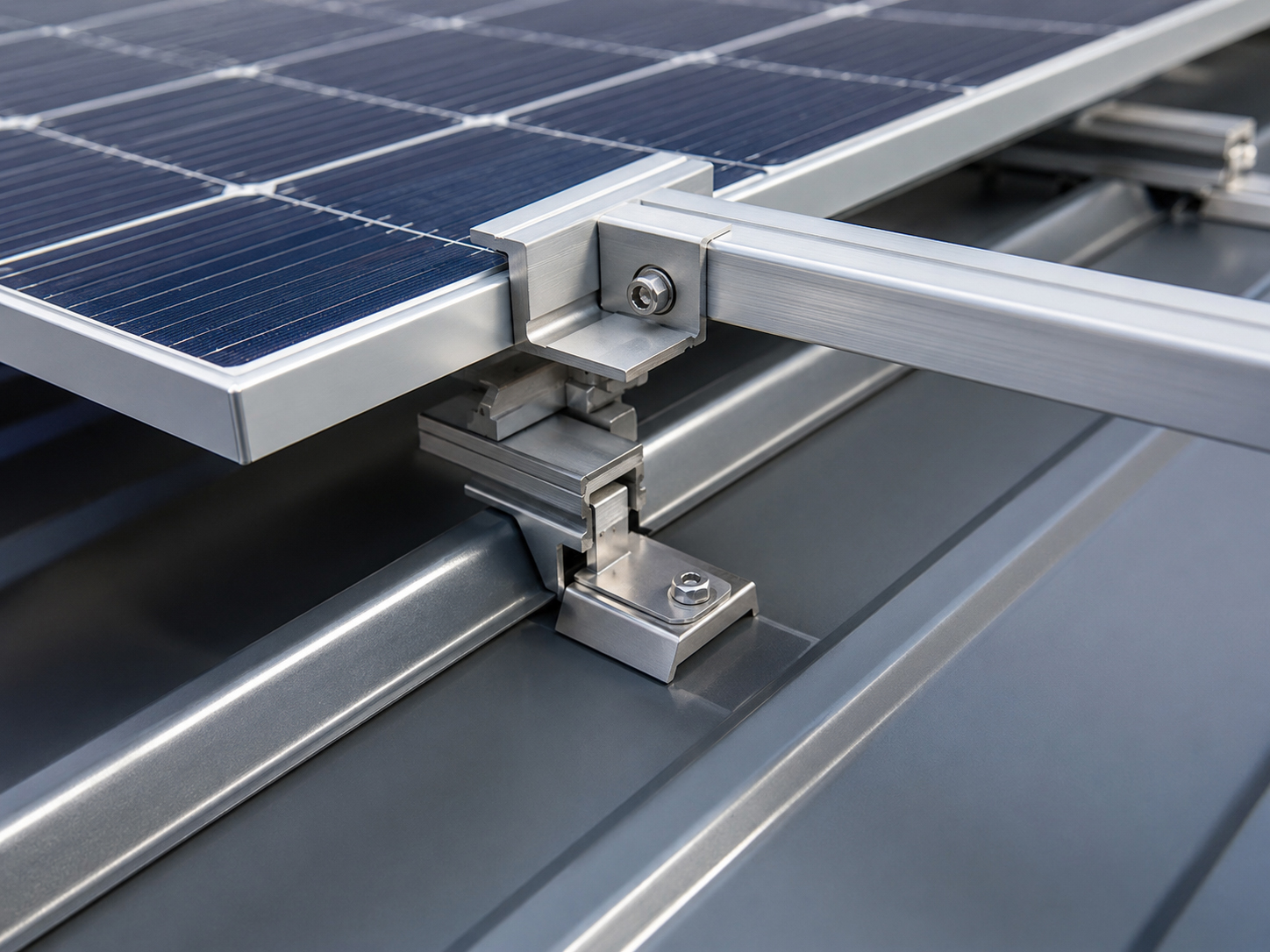
Clamp compatibility and seam strength become central to the load path.
Ballasted Flat Roof
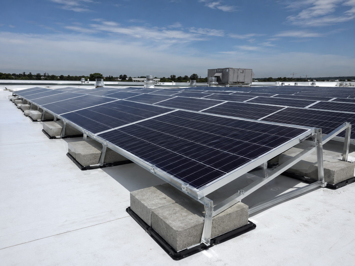
Weight, wind zones, friction, layout, and roof loading must work together.

Ground Mount
Posts, pipe, driven steel, ballast, or foundations must resist open-field wind.
Solar Carports
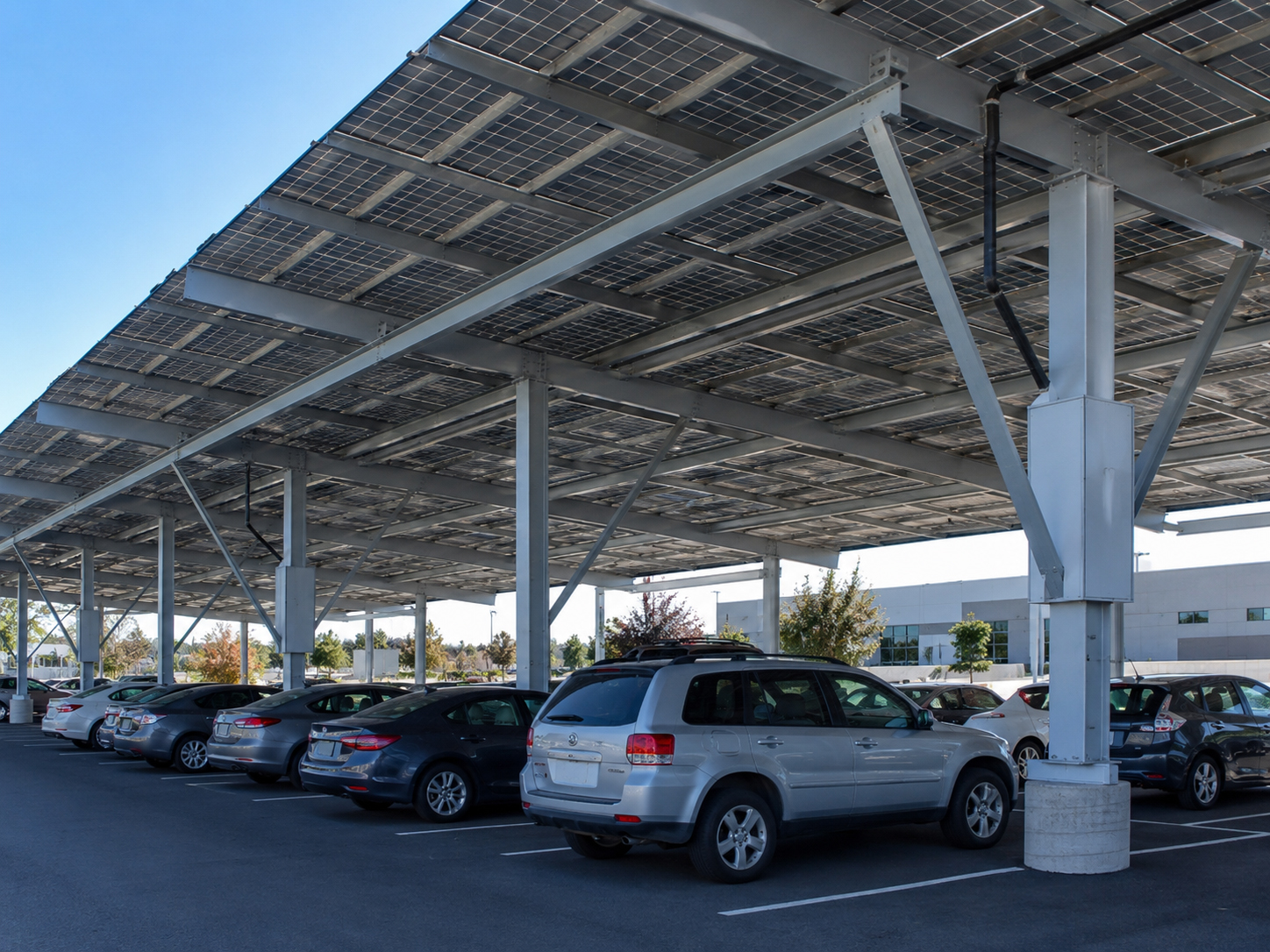
Wind loads move through modules, racking, steel, columns, and footings.

Building-Integrated Solar
Envelope-integrated systems require building-system load path review.

Flat roof ballast
Ballast must be heavy enough for wind and acceptable to the roof.
The ballast design balances two competing truths: the array must stay put, and the roof must not be overloaded.
Ballasted systems use weight and layout to resist movement. But the added load must be acceptable for the roof structure, distributed properly, and coordinated with membrane protection, drainage, access, and inspection requirements.
Practical rule: ballast is not just “blocks on a roof.” It is a wind, weight, membrane, and structural design decision.
Structural review
When the load path is unclear, stop and review.
Solar mounting should not depend on hope, assumptions, or “that looks strong enough.”
Structural review may be needed for unusual roof framing, long spans, older structures, high-wind sites, heavy arrays, ballasted roofs, carports, ground mounts, high-rise solar, or projects with unclear attachment conditions.
Dead load, uplift, lateral load, service load, and long-term weathering.
Follow the load from module frame to roof, framing, ballast, steel, or foundation.
Match the field installation to the approved plan and manufacturer instructions.

Inspection readiness
The load path should be explainable in the field.
A good installation should make sense to the installer, inspector, engineer, roofer, and owner.
Questions for roof-mounted systems
- Where are the rafters or structural targets?
- What fasteners and mounting feet are used?
- How are rails attached and spaced?
- How are clamps placed on the module frame?
- How is waterproofing handled at penetrations?
- What details must be inspected before concealment?
Questions for non-roof systems
- How is the array supported by posts, ballast, or steel?
- How are foundations sized and inspected?
- How are wind uplift and lateral loads resisted?
- How is corrosion or weather exposure addressed?
- How will the system remain serviceable?
- What does the approved plan require?
Plain-language summary: the question is always the same: “If the wind pulls on this panel, where does that force go?”

Permit and inspection
The permit set should tell the same load-path story as the installation.
Inspection becomes easier when the documents and field work agree.
The plan set should identify the mounting method, attachment points, racking system, ballast layout, structural notes, wind assumptions, roof type, equipment layout, and inspection requirements. The field work should match that approved design.
Good field question: “Can this installation be explained from module frame to final support without guessing?”
Homeowner and owner questions
What should owners ask about wind and load paths?
The best questions are practical and direct.
Ask how the panels are held down, where the forces go, whether the roof or structure has been reviewed, how fasteners or ballast are sized, how wind zones are handled, and what the inspector will verify.
Good owner question: “When the wind pulls on the solar panels, how does that force travel safely into my roof, building, ground mount, or carport foundation?”

Related field guide pages
Continue the load path review.
Wind uplift conclusion
The array must be able to explain itself to the wind.
Module to clamp. Clamp to rail. Rail to mount. Mount to structure. Structure to building or foundation. That is the load path story.