
Structure before solar
Solar mounting needs a credible structural path.
Solar panels, rails, clamps, mounting feet, ballast, wind uplift, service loads, ground structures, and carports all need one clear answer: where do the forces go?
The structural question
The solar array must connect to something that can carry it.
A roof surface is not automatically a structure. A racking system is not automatically a load path.
Structural review asks whether the building, roof, rafters, trusses, decking, ballast system, posts, steel frame, or foundation can safely carry the solar installation under real-world conditions. The review should include dead load, wind uplift, lateral forces, attachment spacing, roof condition, and inspection requirements.
SolarMount.com rule: do not let the panel layout outrun the structure. The mounting plan should follow the roof, framing, load path, and approved design.
Structural checklist
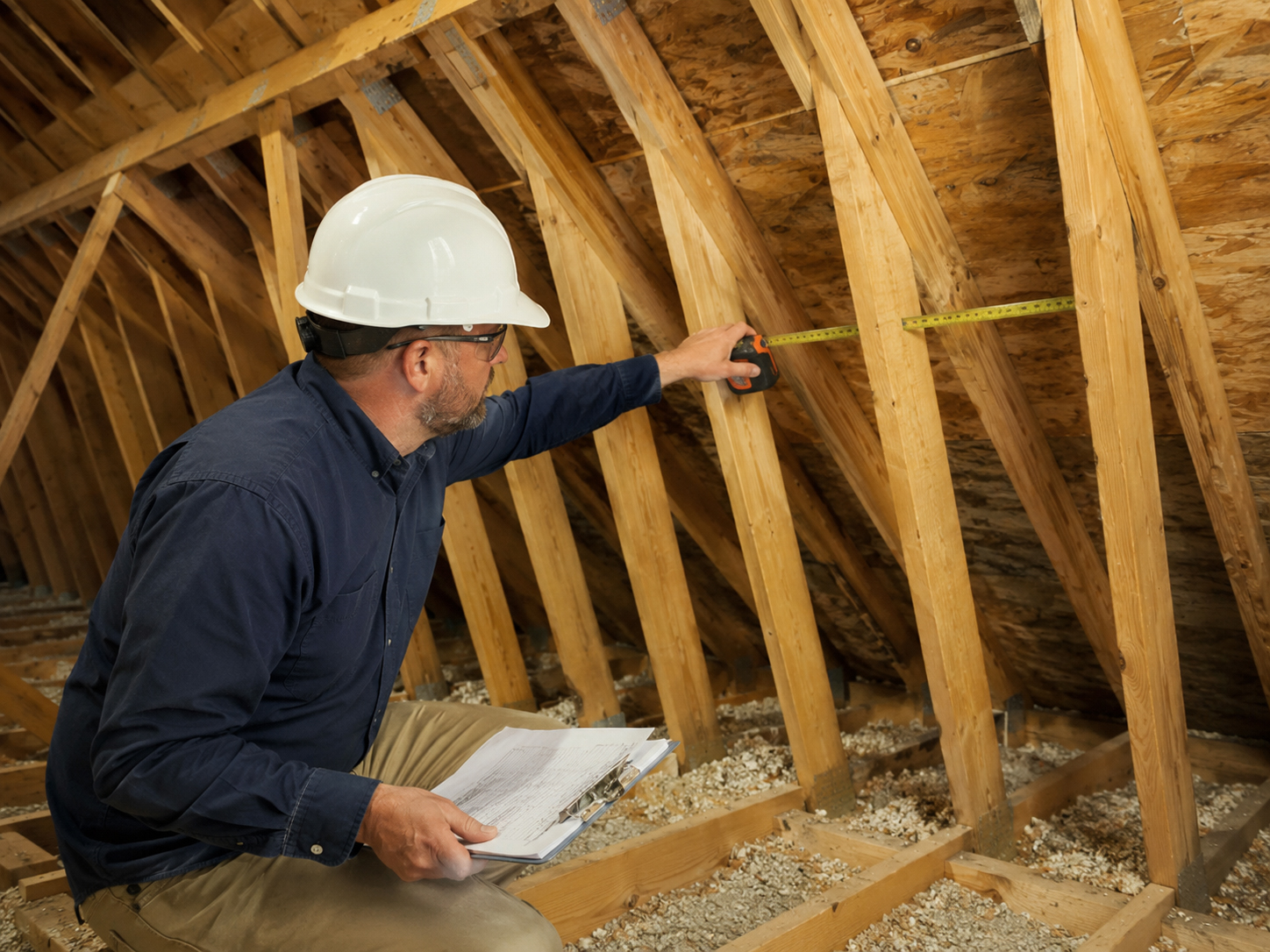
What should be reviewed before solar mounting begins?
Structural review turns assumptions into specific project decisions.
Roof framing
Review rafters, trusses, joists, purlins, decking, spacing, direction, condition, and access for verification where practical.
Dead load
Modules, rails, clamps, mounting feet, conduit, equipment, ballast, and service traffic all add load to the roof or structure.
Wind uplift
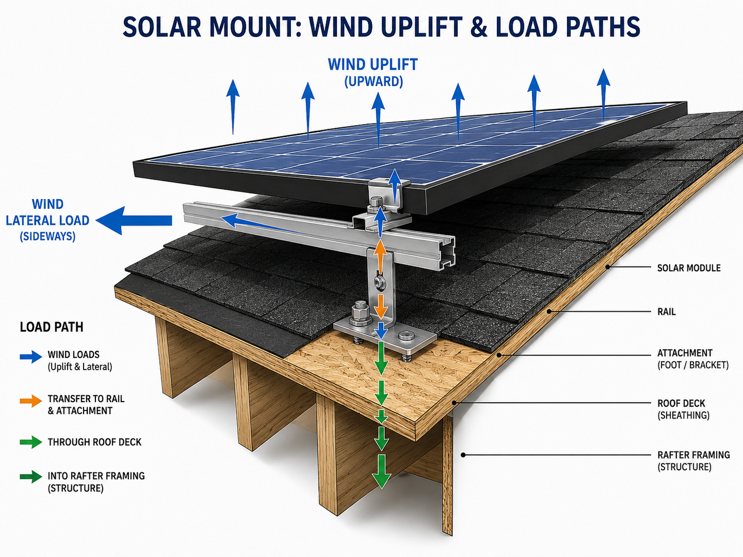
Wind can pull upward and sideways. The mounting system must transfer those forces through an approved load path.
Attachment spacing
Mounting-foot spacing, rail spans, clamp zones, ballast layout, or post spacing must follow the approved method.
Roof condition
Sagging, old repairs, damaged decking, brittle materials, or soft areas can change the structural and waterproofing conversation.
Engineering need
Some projects require licensed engineering review, especially unusual roofs, heavy systems, ballast, carports, ground mounts, or unclear framing.
Sloped roof structure
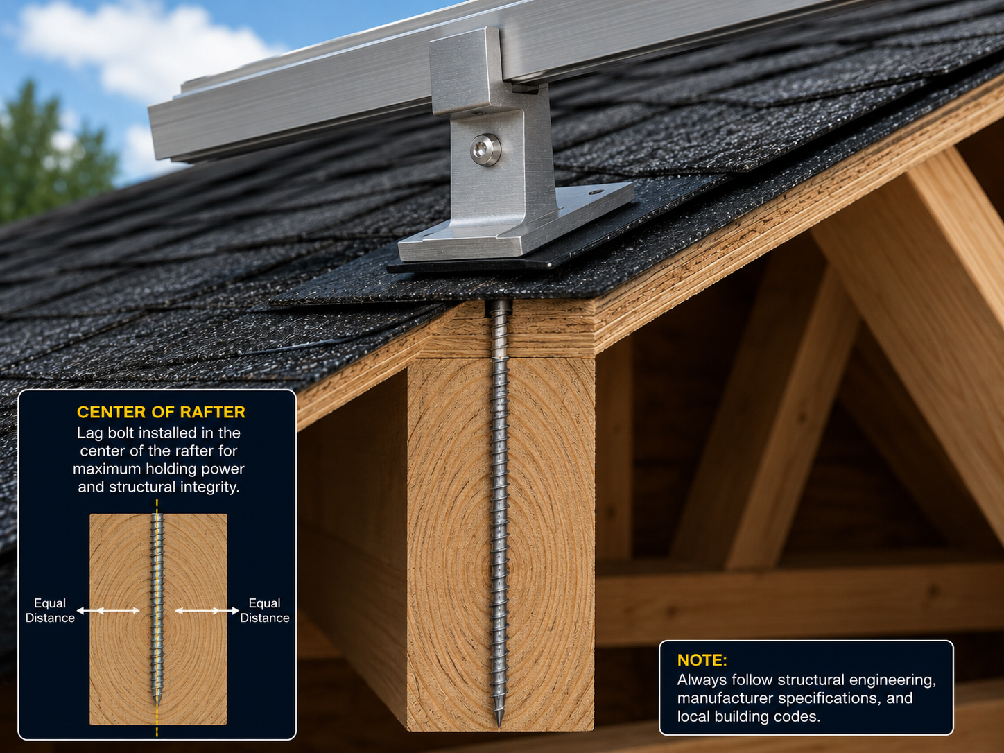
On many roofs, the rafter is the attachment target.
The roof covering sheds water. The framing below carries the mounting loads.
For many sloped-roof installations, solar mounting feet are fastened into rafters or approved framing. That means the crew must understand rafter direction, spacing, condition, attachment location, pilot-hole preparation, flashing, sealant, and inspection timing.
Practical rule: a fastener should not be a search tool. Find the structure before drilling into the roof.
When deeper review is needed
Some projects are not routine.
The need for structural review increases when the roof, load, or mounting method is unusual.
Conditions that deserve extra attention
- Older roof framing or unknown framing condition.
- Long spans, vaulted ceilings, cathedral ceilings, or difficult attic access.
- Sagging roof planes, old repairs, soft decking, or visible structural concerns.
- Tile roofs with uncertain underlayment or access issues.
- Wood shake roofs, unusual roof geometry, or mixed roof materials.
- Large systems, high-wind sites, carports, ground mounts, or ballasted flat roofs.
Questions structural review should answer
- What is the full added load?
- Where are the attachment points?
- How does wind uplift travel into the structure?
- Does the roof framing match the assumed design?
- Are reinforcements, layout changes, or different mounting methods needed?
- What must be documented for the permit and inspection path?
Important: this page is educational. Actual structural review, engineering decisions, roof-load calculations, fastener selection, ballast design, foundation sizing, reinforcement, and inspection requirements must follow the approved plan set, manufacturer instructions, engineering requirements, local code, fire code, and qualified professional judgment.
Load path logic
Follow the load from panel to structure.
If the path cannot be explained, it has not been reviewed enough.
A solar mounting load path may run from module to clamp, clamp to rail, rail to mounting foot, mounting foot to lag bolt, lag bolt to rafter, and rafter to the building frame. On flat roofs, it may run through ballast and roof structure. On carports, it travels through steel and foundations.
Dead load, wind uplift, lateral load, service load, and long-term movement.
Follow the force through each connection into the building or ground.
Confirm the installation matches the approved plan and inspection requirements.
Reinforcement options
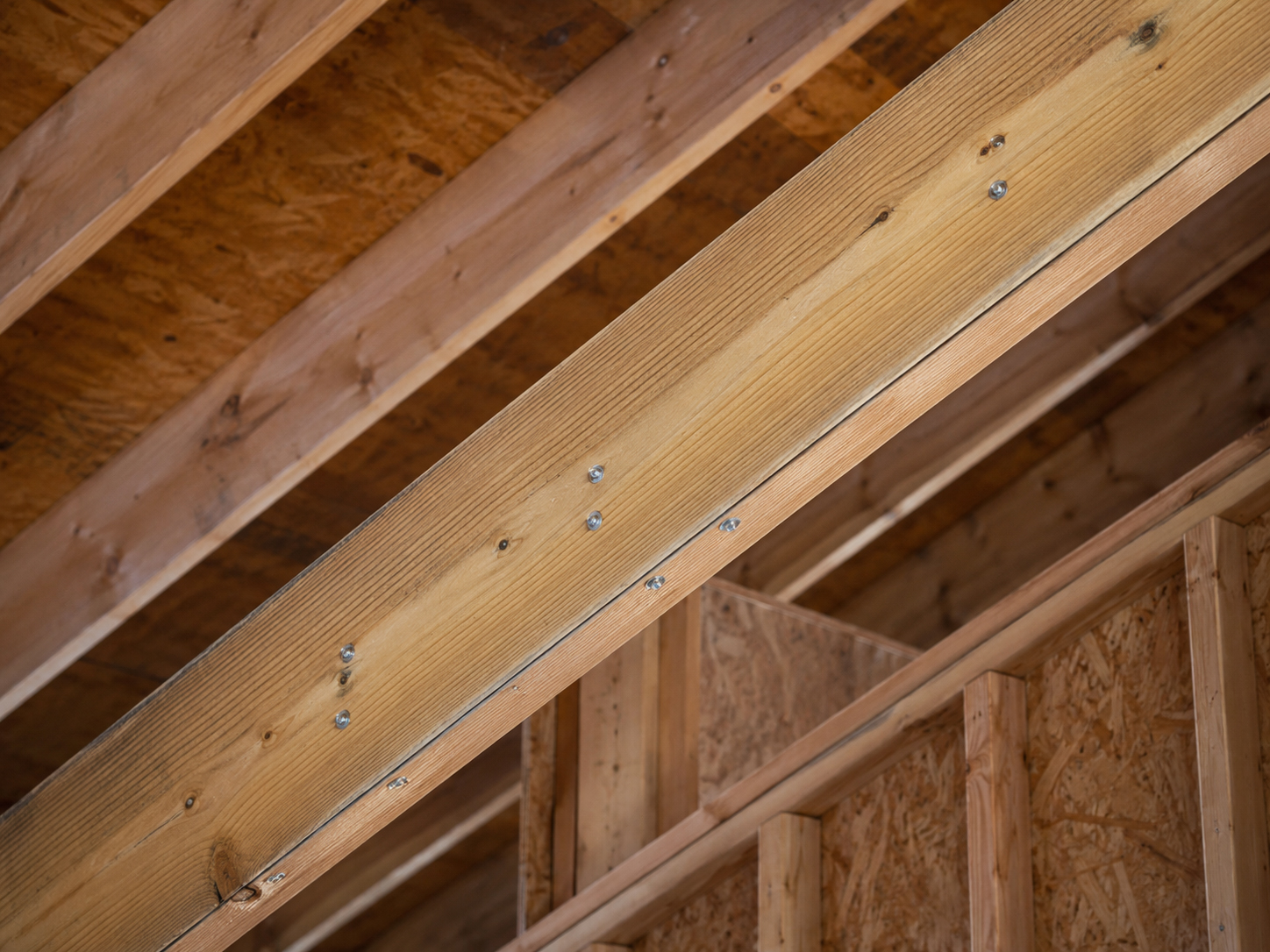
Sometimes the answer is reinforcement, not guesswork.
If the existing structure does not clearly support the planned attachment, the design should adapt.
Some projects may need sistered rafters, blocking, layout changes, different attachment spacing, additional review, or another mounting method. The right approach depends on the actual roof, structure, approved plan, and engineering requirements.

Flat roof and ballast
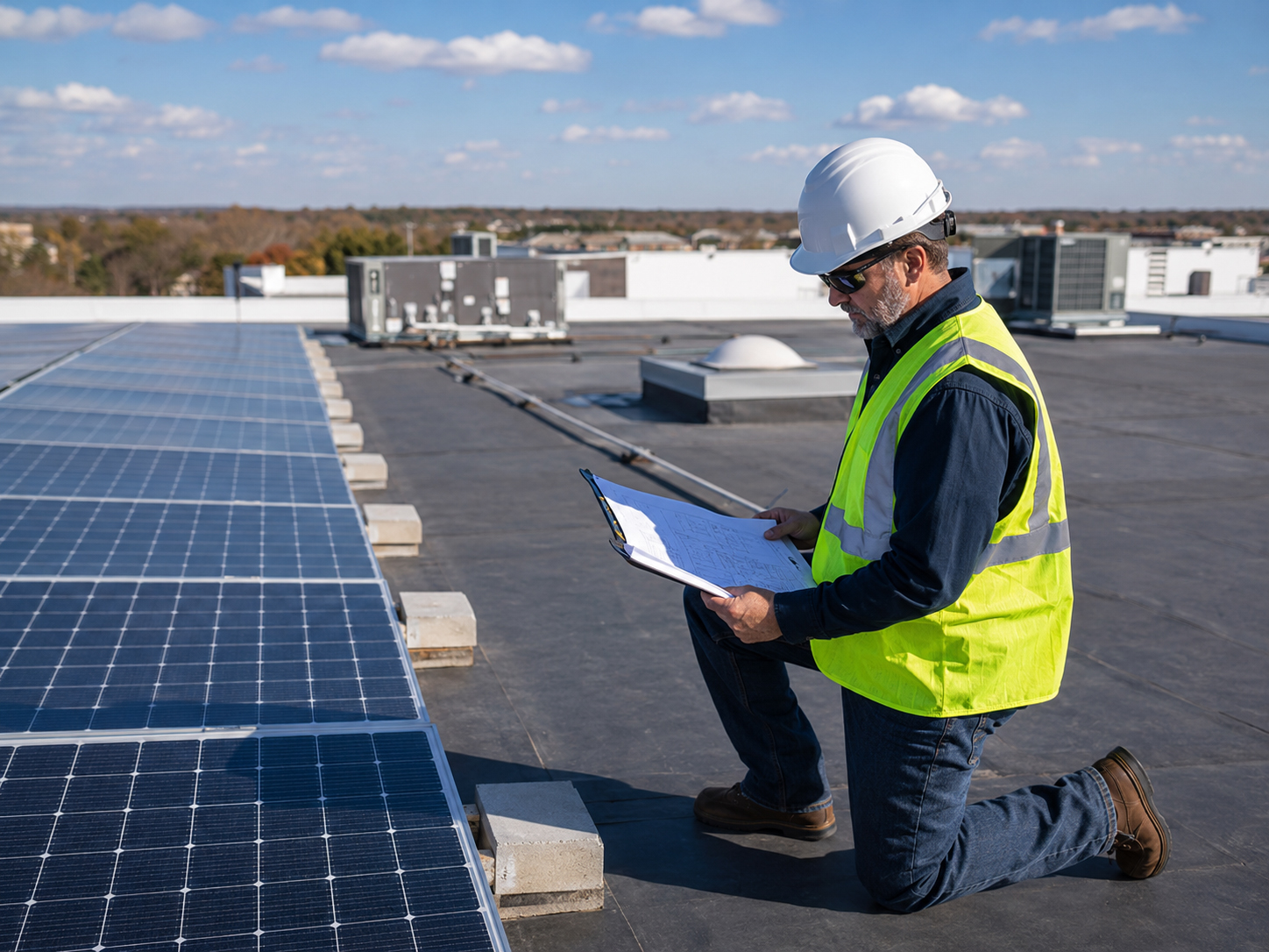
Ballasted flat roofs are structural conversations.
Ballast may reduce penetrations, but it adds weight.
Commercial flat roof systems can require review of total ballast weight, concentrated load points, roof framing, membrane protection, wind zones, parapets, drainage, and access pathways. Space on a flat roof is not the same as structural capacity.
Practical rule: ballast is not “free weight.” The building must be able to carry it, and the wind design must explain why it stays put.
Carports and ground mounts
When solar becomes a structure, engineering becomes central.
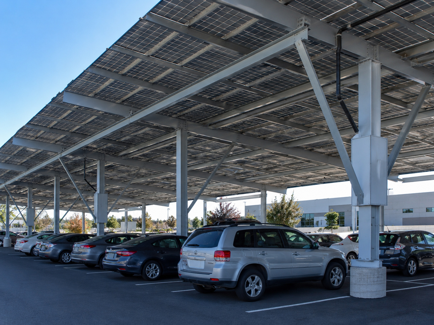
Ground mounts and carports transfer forces into posts, steel, soil, and foundations.
Solar carports, ground-mounted arrays, driven steel posts, pipe structures, ballast-mounted systems, and building-integrated solar are not merely equipment installations. They are structural systems with site-specific load paths.
Posts, pipe, driven steel, ballast, or foundations must resist wind and gravity.
Modules transfer loads through racking, steel, columns, and footings.
Facade or envelope systems require building-system review.
Owner questions
What should owners ask about structural review?
The best questions are plain, practical, and hard to dodge.
Roof-mounted system questions
- Where are the rafters or structural supports?
- How are mounting feet attached?
- How much load is being added?
- How does wind uplift travel into the structure?
- Does the roof show sagging, damage, or old repairs?
- Does this roof need engineering review before solar?
Flat roof, carport, and ground questions
- How much ballast or structural steel is being added?
- How are foundations or posts designed?
- How are roof edge and wind zones handled?
- How are concentrated loads distributed?
- What does the approved plan say?
- What will the inspector verify?
Good owner question: “Can you explain the structural path from the solar panel all the way into the roof, building, ground, or foundation?”

Permit and inspection
The structural story should match the approved plan.
Field work should not improvise a load path.
The permit set should identify mounting method, attachment pattern, structural notes, ballast layout where applicable, foundation details where applicable, roof type, racking system, and inspection requirements. The installation should follow that approved design.
Plain-language summary: if the plan cannot explain the load path, the field crew should not invent one on installation day.
Related field guide pages
Continue the structural review.
Structural review conclusion
The structure must answer before the array is installed.
Solar mounting needs a clear support path for weight, wind, service loads, ballast, posts, steel, rafters, and foundations. The plan and the field work must agree.