Ground mount field guide
Ground mounted solar is still a structure.
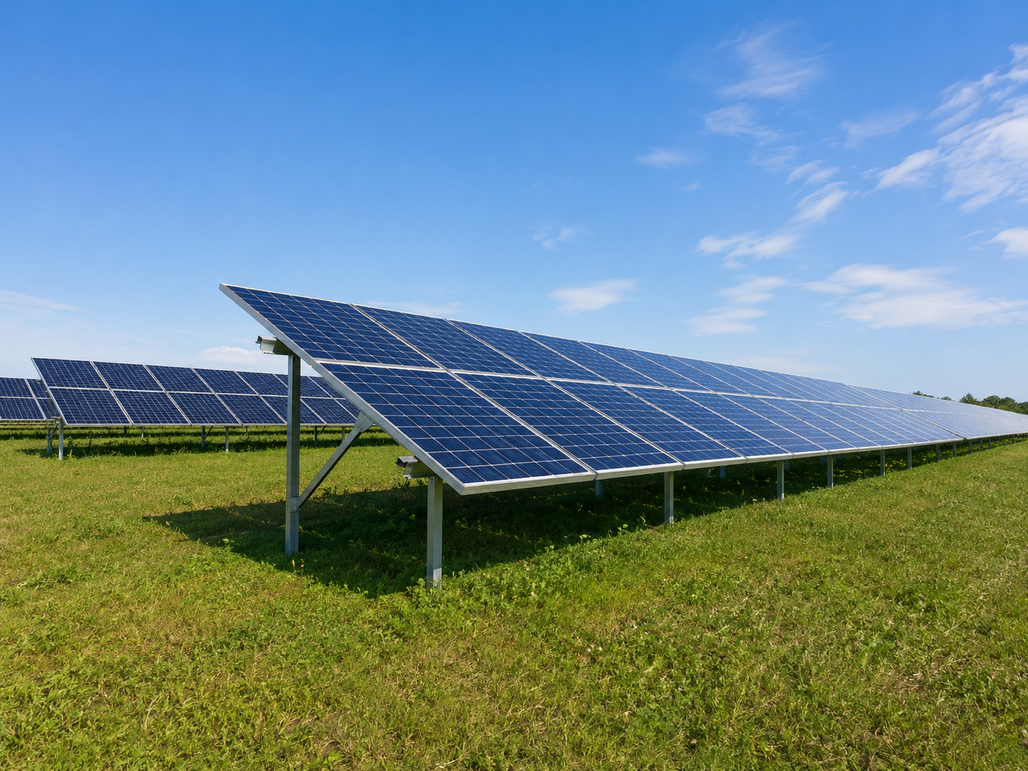
When the roof is not the answer, the ground may be. But a ground mounted solar system still requires serious planning: layout, posts, foundations, pipe, ballast, trenching, inverter placement, wire paths, grading, drainage, access, and inspection.
Not just panels in a field
A ground mount needs a foundation, load path, and service plan.
Moving the solar off the roof does not remove construction responsibility.
Ground mounted solar changes the questions. Instead of roof age and rafters, the project must review soil, slope, setbacks, foundations, posts, trenching, conduit, inverter location, wire sizing, equipment access, mowing or vegetation control, drainage, and future maintenance.
SolarMount.com rule: a ground mounted array is not just solar equipment. It is a site structure with foundations, electrical pathways, access needs, and inspection requirements.
Ground mount checklist
What should be reviewed before installation?
A ground mount can be easier to service than roof solar, but only when the site plan is disciplined.
Site layout
Review available land, setbacks, property lines, utility easements, shade, slope, drainage, access, and visual impact.
Foundation method
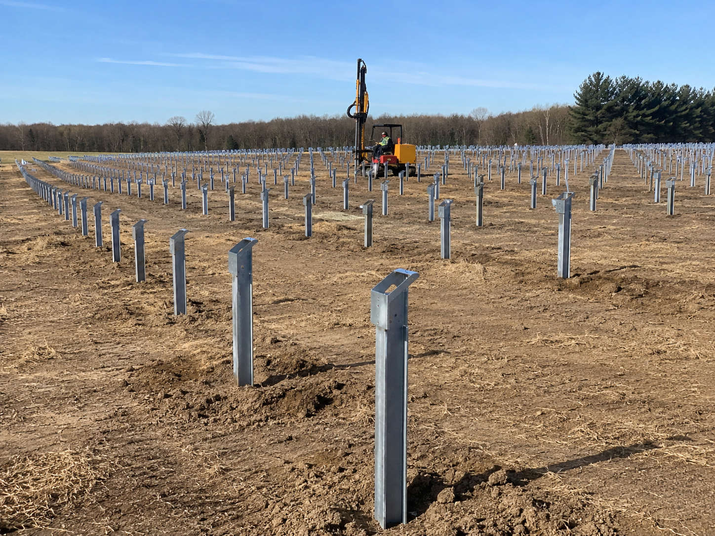
Posts, driven steel, pipe, concrete piers, ballast, or other foundation methods must match the site conditions and approved design.
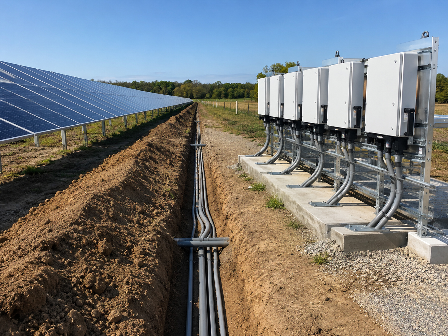
Trenching
Underground conduit routes, wire distance, voltage drop, depth, protection, utility conflicts, and restoration should be planned early.
Inverter placement
Inverters, disconnects, combiner boxes, service equipment, and utility interconnection should be located for safety and serviceability.
Wind exposure
Open-field arrays can face strong wind. Posts, rails, foundations, and module layout must satisfy the approved load path.
Maintenance access
Leave practical access for mowing, vegetation control, cleaning, inspection, module replacement, and electrical service.
Foundation decision
The post or foundation method controls the ground mount story.
The solar array is only as durable as the support system below it.
Ground mount structures may use driven steel posts, schedule 40 pipe, concrete piers, ballast, or engineered foundations depending on the soil, slope, wind exposure, array size, equipment choice, and local requirements. The correct method depends on site-specific review.
Practical rule: do not design the array in the air. Design the support system from the ground up.
Foundation options
Different ground mount methods solve different site problems.
The goal is not to pick the strongest-sounding method. The goal is to choose the method that fits the site.
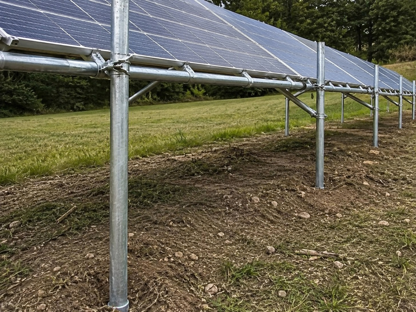
Schedule 40 Pipe
Pipe-based ground mount concepts for sturdy, serviceable solar structures.
Driven Steel Posts
Driven posts can reduce concrete but require soil and engineering review.
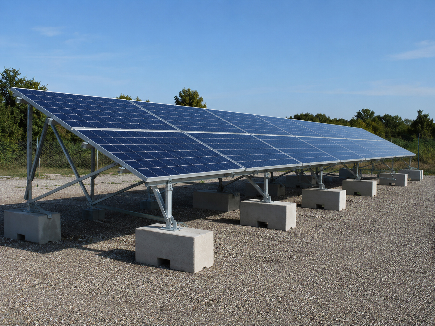
Ballast Mounted Ground Solar
Ballast can avoid deep foundations but adds weight and wind-design questions.
Important: this page is educational. Actual ground mount foundation design, post spacing, pipe sizing, ballast, soil review, wind loading, trenching, grounding, electrical work, and inspection requirements must follow the approved plan set, manufacturer instructions, engineering requirements, utility requirements, and local code.
Trenching and equipment
The trench is part of the solar design.
Ground mounted solar usually moves electricity across the property before it reaches the building.
Trenching affects conduit size, wire sizing, voltage drop, service equipment location, utility interconnection, restoration, permitting, and safety. The array location must be planned with the electrical route in mind, not as an afterthought.
Choose a location with sunlight, access, soil suitability, and practical electrical routing.
Review distance, depth, conduit, wire size, obstacles, and restoration.
Locate inverters, disconnects, combiners, and service equipment for safety and service.
Wind and load path
Open-field solar faces wind directly.
A ground array must resist wind, gravity, soil movement, corrosion, and long-term weather exposure.
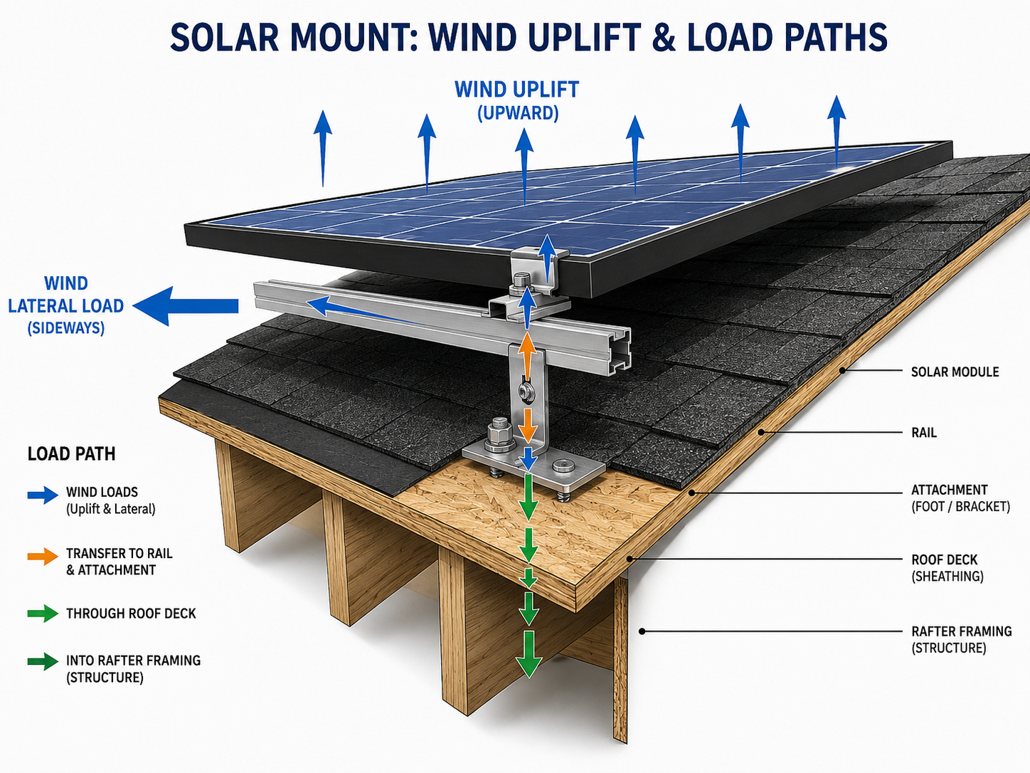
Wind Uplift
Wind can pull, push, twist, and rack the array. The structure must resist it.

Structural Review
Ground mount structures still need a credible support and load path.
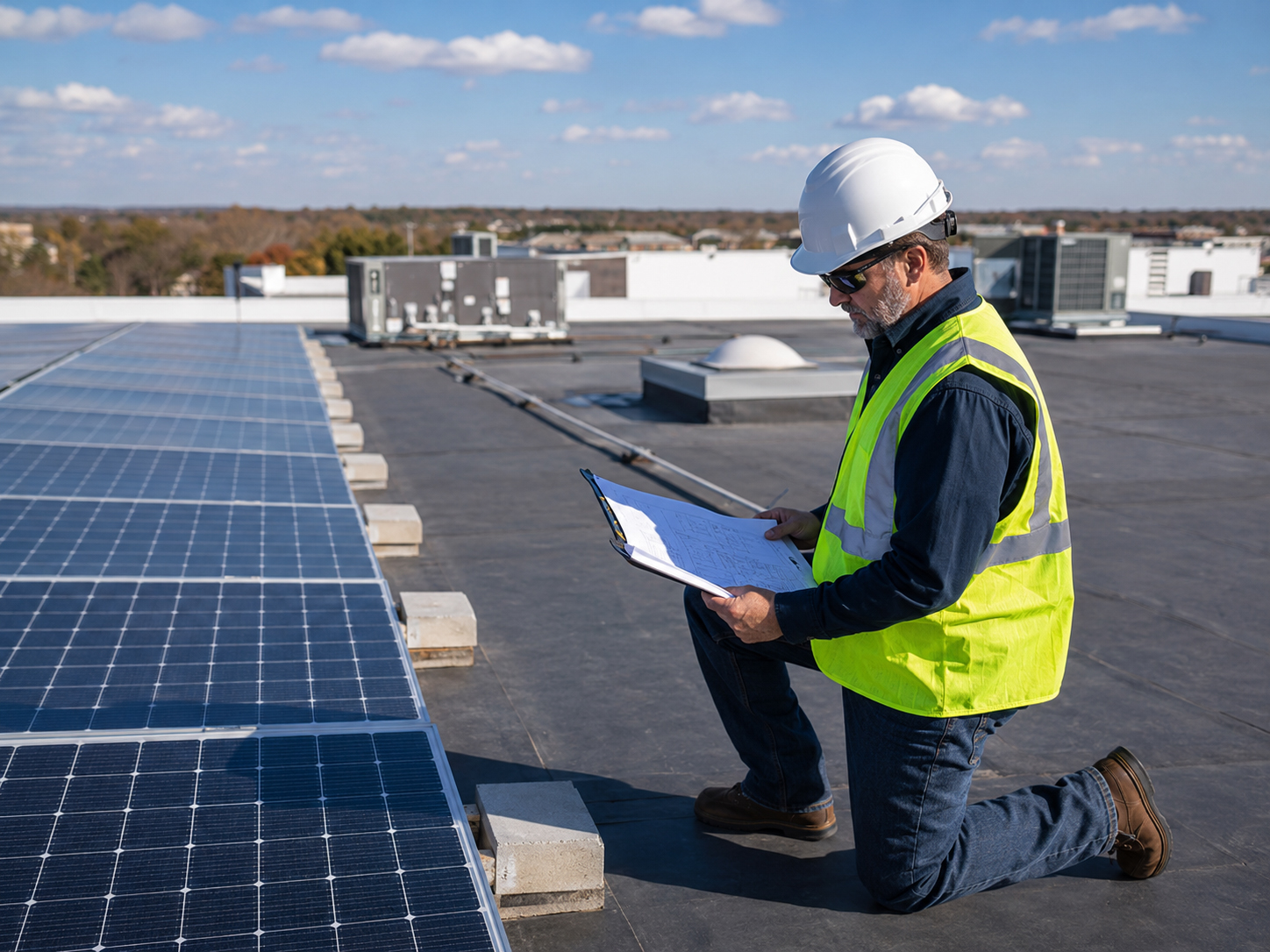
Load Review
Solar structures must be reviewed for forces beyond simple panel weight.
Plain-language summary: a ground mount is not safer just because it is not on the roof. It still has to survive wind, soil, weather, electrical requirements, and maintenance over time.
Ballast-mounted ground solar
Ballast can avoid digging, but it does not avoid engineering.
Heavy systems still need wind, soil, drainage, access, and inspection review.
Ballast-mounted ground solar can be useful when soil disturbance, foundations, or site conditions make other approaches difficult. But ballast adds weight and requires careful wind design, equipment layout, drainage review, and long-term stability review.
Practical rule: ballast is not a shortcut around design. It is a different design problem.
Site serviceability
The ground mount should be easy to reach years later.
A good ground array is not only installed well. It is maintained well.
Service access should be considered before installation: module access, row spacing, vegetation control, cleaning, inverter access, disconnect access, trench records, equipment labeling, and safe pathways for future work.
Tight layouts can make future maintenance harder and more expensive.
Grass, weeds, dust, and animals can affect access and long-term performance.
Trench and conduit records matter for future repairs and site work.
Homeowner and property-owner questions
What should be asked before choosing a ground mount?
A ground mount can be the right answer when the site has the right space, access, and electrical path.
Site questions
- Where is the best solar exposure?
- What setbacks, easements, or zoning limits apply?
- Is the ground level, sloped, rocky, sandy, or unstable?
- Where will water drain during storms?
- How will vegetation be controlled?
- Can service crews reach the array safely?
Electrical questions
- How far is the array from the service equipment?
- Where will inverters and disconnects be located?
- What trench route is practical?
- How will voltage drop and wire sizing be handled?
- Are there existing underground utilities?
- How will the trench and conduit path be documented?
Good homeowner question: “If we put solar on the ground instead of the roof, where will the trench run, where will the inverters go, and how will we service the array later?”

Permit and inspection
Ground mounts need clear plans and inspection readiness.
The plan set should explain the structure, electrical route, equipment layout, and site work.
A ground mounted solar permit may need to address structural supports, foundations, setbacks, trenching, electrical equipment, grounding, wire sizing, labeling, utility interconnection, and final inspection requirements.
Plain-language summary: the ground mount should be explainable to the installer, inspector, property owner, electrician, and future service team.
Related field guide pages
Continue the ground mount review.
Ground mount conclusion
When the roof is not the answer, design from the ground up.
Ground mounted solar should begin with site layout, foundations, posts, trenching, inverter placement, wind exposure, access, drainage, electrical pathway, and inspection planning.